DTC P3190 Poor Engine Power |
DTC P3191 Engine dose not Start |
DTC P3193 Fuel Run Out |
| DTC No. | DTC Detection Condition | Trouble Area |
| PP3190 | Following conditions continue at a fixed engine RPM or a fixed length of time:
|
|
| PP3191 | Following conditions continue at a fixed engine RPM or a fixed length of time:
|
|
| PP3193 | Following conditions are met:
|
|
| Related DTCs | P3190: Poor engine power P3191: Engine does not start P3193: Fuel run out |
| Required sensors/components | Main sensors: Crankshaft position sensor Related sensors: HV control ECU |
| Frequency of operation | Continuous |
| Duration | 100 engine revolutions and 6 seconds |
| MIL operation | Immediately |
| Sequence of operation | None |
| The monitor will run whenever the following DTCs are not present | None |
| Fuel cut operation | Not operated |
| Engine speed | 750 rpm or more (varies with engine coolant temperature) |
| Time for low engine torque | 100 engine revolutions or more, or 6 seconds or more (varies with engine coolant temperature) |
| Engine start no-determination time (receive from HV ECU) | 100 engine revolutions or more, and 6 seconds or more (varies with engine coolant temperature) |
| Time for low engine torque or Engine start no-determination time | 100 engine revolutions or more, and 6 seconds or more (varies with engine coolant temperature) |
| 1.CHECK OTHER DTC OUTPUT (IN ADDITION TO DTC P3190, P3191 AND/OR P3193) |
Connect the intelligent tester to the DLC3.
Turn the power switch ON (IG).
Turn the intelligent tester ON.
Enter the following menus: DIAGNOSIS / ENHANCED OBD II / DTC INFO / CURRENT CODES.
Read DTCs.
| Display (DTC output) | Proceed to |
| P3190, P3191 and/or P3193 | A |
| P3190, P3191 and/or P3193, and other DTCs | B |
|
| ||||
| A | |
| 2.CHECK SHORTAGE OF FUEL |
|
| ||||
| OK | |
| 3.CHECK AIR INDUCTION SYSTEM |
|
| ||||
| OK | |
| 4.CHECK FOR UNUSUAL NOISE OR VIBRATION WHEN STARTING ENGINE OR REVVING UP |
|
| ||||
| OK | |
| 5.CHECK FUEL PRESSURE |
|
| ||||
| OK | |
| 6.INSPECT MASS AIR FLOW METER |
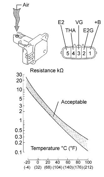 |
Remove the mass air flow meter.
Inspect output voltage.
Apply battery voltage across terminals +B and E2G.
Connect the positive (+) tester probe to terminal VG, and negative (-) tester probe to terminal E2G.
Blow air into the mass air flow meter, and check that the voltage fluctuates.
| Tester Connection | Specified Condition |
| 3 (VG) - 2 (E2G) | Sensor output voltage fluctuates between 0.3 V and 4.8 V |
Inspect resistance.
Measure the resistance between the terminals of the mass air flow meter.
| Tester Connection | Specified Condition |
| 4 (THA) - 5 (E2) | 13.6 to 18.4 kΩ at -20°C (-4°F) |
| 4 (THA) - 5 (E2) | 2.21 to 2.69 kΩ at 20°C (68°F) |
| 4 (THA) - 5 (E2) | 0.49 to 0.67 kΩ at 60°C (140°F) |
Reinstall the mass air flow meter.
|
| ||||
| OK | |
| 7.INSPECT ENGINE COOLANT TEMPERATURE SENSOR |
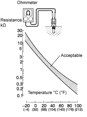 |
Remove the engine coolant temperature sensor.
Measure the resistance between the terminals of the engine coolant temperature sensor.
| Tester Connection | Specified Condition |
| 1 - 2 | 2 to 3 kΩ at 20°C (68°F) |
| 1 - 2 | 0.2 to 0.4 kΩ at 80°C (176°F) |
Reinstall the engine coolant temperature sensor.
|
| ||||
| OK | |
| 8.INSPECT CRANKSHAFT POSITION SENSOR |
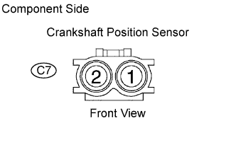 |
Disconnect the C7 crankshaft position sensor connector.
Measure the resistance between the terminals of the crankshaft position sensor connector.
| Tester Connection | Specified Condition |
| 1 - 2 | 985 to 1,600 Ω at cold |
| 1 - 2 | 1,265 to 1,890 Ω at hot |
Reconnect the crankshaft position sensor connector.
|
| ||||
| OK | |
| 9.INSPECT CAMSHAFT POSITION SENSOR |
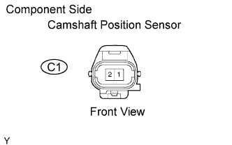 |
Disconnect the C1 camshaft position sensor connector.
Measure the resistance between the terminals of camshaft position sensor connector.
| Tester Connection | Specified Condition |
| 1 - 2 | 1,630 to 2,740 Ω at cold |
| 1 - 2 | 2,065 to 3,225 Ω at hot |
Reconnect the camshaft position sensor connector.
|
| ||||
| OK | |
| 10.INSPECT THROTTLE CONTROL MOTOR |
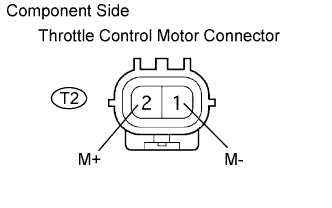 |
Disconnect the throttle control motor connector.
Using an ohmmeter, measure the motor resistance between terminals 1 (M-) and 2 (M+).
| Tester Connection | Specified Condition |
| 1 - 2 | 0.3 to 100 Ω at 20°C (68°F) |
|
| ||||
| OK | |
| 11.INSPECT THROTTLE POSITION SENSOR |
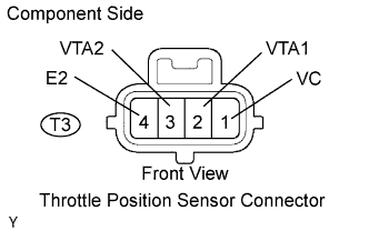 |
Disconnect the throttle position sensor connector.
Measure the resistance between the terminals of the throttle position sensor.
| Tester Connection | Specified Condition |
| 1 (VC) - 4 (E2) | 1.2 to 3.2 kΩ at 20°C (68°F) |
| 2 (VTA1) - 4 (E2) | 1.8 to 10.5 kΩ at 20°C (68°F) |
| 3 (VTA2) - 4 (E2) | 1.8 to 10.5 kΩ at 20°C (68°F) |
|
| ||||
| OK | ||
| ||
